Build a Smart Door Lock Using ESP32 and RFID: A Complete Beginner’s DIY Guide
Securing physical spaces such as your home or office with smart technology is no longer a futuristic idea. Thanks to affordable microcontrollers like the ESP32 and popular wireless identification technologies like RFID, creating a secure, efficient, and expandable smart door lock system is now well within reach for hobbyists and beginners.
This article will walk step-by-step through the entire design and build process for a Smart Door Lock using ESP32 and RFID, carefully explaining each component, wiring detail, programming step, practical testing, troubleshooting, and future expansions. By the end, a beginner will have gained not only a reliable working prototype but valuable hands-on skills in microcontrollers, embedded programming, IoT systems, and electronics.
Why Build a Smart Door Lock?
Traditional mechanical locks are reliable but come with inherent limitations: loss of keys, copying keys by unauthorized parties, and inconvenience of managing multiple users. A smart door lock mitigates these problems by using digital authentication and automation. Here are the benefits:
- Keyless Access: Users can unlock the door by simply tapping an RFID card or fob, eliminating the need for physical keys.
- Multi-user Management: Easily add or remove access by programming new RFID tags without re-keying locks.
- Security Alerts: Add logging and alerting for unauthorized access attempts or lock status changes for peace of mind.
- Integration Potential: With Wi-Fi-enabled ESP32, this can be integrated into home automation or smartphone apps for remote control and monitoring.
Building your own lock system also promotes learning about hardware, software, and cybersecurity fundamentals, making it a rewarding project for makers.
Understanding the Core Components
Before getting hands-on, understanding the fundamental components is key.
ESP32 Microcontroller – The Brain
ESP32 is a powerful and affordable microcontroller with built-in Wi-Fi and Bluetooth connectivity, making it ideal for IoT and embedded projects. Features relevant here include:
- Multiple GPIO pins for sensor and actuator connections.
- Integrated SPI interface to communicate with RFID readers.
- Real-time processing for quick decision-making on card scans.
- Support for Arduino IDE, simplifying programming for beginners.
The ESP32 acts as the central controller that reads RFID input, verifies access, and controls the locking mechanism.
RFID Technology – Card-Based Authentication
RFID (Radio Frequency Identification) uses electromagnetic fields to identify and track tags attached to objects. For this project:
- The MFRC522 module is commonly used and affordable, communicating over SPI with the ESP32.
- RFID tags/cards contain unique IDs (UIDs) that are wirelessly read without contact.
- The ESP32 compares the UID against authorized IDs stored onboard.
In essence, RFID is the ‘digital key’ system your smart lock will employ.
Lock Actuation – Solenoid or Servo
The lock actuator physically controls the door locking mechanism:
- Solenoid Lock: Uses electromagnetic force to move a bolt in or out, requiring a 12V power supply and relay control. Commonly seen in electric door strikes.
- Servo Motor: Simpler for prototyping, a servo can rotate a latch or lever to unlock. Runs on 5-6V and directly controlled by ESP32 PWM pins.
For a fully secure system, solenoids or electromagnetic locks are preferred. For learning and demonstration, servo motors are lighter and safer.
Relay Module
As the solenoid lock operates at higher voltage and current than ESP32 GPIO pins can directly provide, a relay module acts as an electrically-isolated switch, enabling the ESP32 to safely control the lock.
Complete List of Materials and Tools
| Component | Description/Specs | Quantity | Purpose |
| ESP32 Development Board | ESP32 DevKit V1 or NodeMCU-32S | 1 | Microcontroller |
| RFID RC522 Module | SPI interface, 3.3V | 1 | RFID tag reading |
| RFID Tags / Cards | 13.56 MHz frequency | 2-3 | User authentication |
| Solenoid Lock | 12V DC electric lock | 1 | Physical lock mechanism |
| Relay Module | 5V, single channel relay | 1 | Switch for solenoid |
| Power Supply | 12V DC adapter, 2A | 1 | Power solenoid lock |
| Breadboard & Jumper wires | Various jumper cables | 1 set | Prototyping connections |
| LED Indicators (optional) | 3mm or 5mm LEDs (green/red) | 2 | Visual access feedback |
| Buzzer (optional) | 5V piezo buzzer | 1 | Audible access feedback |
| LCD Display (optional) | I2C 16×2 OLED or LCD | 1 | User messages |
Tools: USB cable, PC with Arduino IDE installed, multimeter for testing, soldering iron (optional for permanent connections).
Detailed Wiring & Circuit Connections
Step 1: Connect RFID RC522 to ESP32
| RFID Pin | ESP32 Pin (Example) | Notes |
| SDA (SS) | GPIO 21 | SPI slave select |
| SCK | GPIO 18 | SPI clock |
| MOSI | GPIO 23 | SPI data out |
| MISO | GPIO 19 | SPI data in |
| RST | GPIO 22 | Reset pin |
| 3.3V | 3.3V | Power supply |
| GND | GND | Ground |
Step 2: Relay Module to ESP32
| Relay Pin | ESP32 Pin (Example) | Notes |
| IN | GPIO 5 | Control signal |
| VCC | 5V | Power for relay |
| GND | GND | Common ground |
Note: Relay VCC and control signals usually require 5V logic; check relay specs and provide external power if needed.
Step 3: Solenoid Lock to Relay & Power Supply
| Lock Terminal | Connection | Notes |
| + (Positive) | Normally Open (NO) of Relay | Power switched line |
| – (Negative) | Negative of 12V power supply | Common ground |
| Relay Common | Positive of 12V power supply | Relay common pin |
Ensure a common ground between ESP32 and power supply to avoid floating signals.
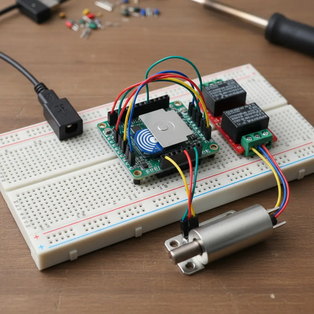
Wiring Diagram (Visual Reference)
[Place an illustrative circuit diagram here showing all connections on a breadboard or schematic view, depicting ESP32, RFID module, relay module, solenoid lock, and power supply connections.]
Programming the ESP32 with Arduino IDE
The program consists of the following key parts:
- Initialize SPI and RFID reader.
- Define authorized RFID card UIDs in code.
- Continuously scan for nearby RFID tags.
- Match scanned UID with authorized list.
- Activate relay to unlock if authenticated, else deny access.
- Provide optional serial monitor, LED, buzzer, or LCD feedback.
Step-by-Step Code Explanation
cpp
#include <SPI.h>
#include <MFRC522.h>
// Pin Definitions
#define SS_PIN 21
#define RST_PIN 22
#define RELAY_PIN 5
MFRC522 rfid(SS_PIN, RST_PIN);
// Authorized RFID UIDs (example)
byte authorizedUID[][4] = {
{0xA3, 0x5B, 0x4D, 0x29},
{0xB4, 0x6A, 0x3C, 0x51},
};
const int authorizedUIDCount = 2;
void setup() {
Serial.begin(115200);
SPI.begin();
rfid.PCD_Init();
pinMode(RELAY_PIN, OUTPUT);
digitalWrite(RELAY_PIN, LOW); // Initially lock engaged
Serial.println(“Smart Lock Initialized. Scan your RFID tag.”);
}
void loop() {
if (!rfid.PICC_IsNewCardPresent() || !rfid.PICC_ReadCardSerial()) {
return; // No card present
}
Serial.print(“Card UID: “);
for (byte i = 0; i < rfid.uid.size; i++) {
Serial.print(rfid.uid.uidByte[i], HEX);
Serial.print(” “);
}
Serial.println();
if (isAuthorized(rfid.uid.uidByte)) {
Serial.println(“Access Granted”);
unlockDoor();
} else {
Serial.println(“Access Denied”);
}
rfid.PICC_HaltA(); // Halt PICC (card)
}
bool isAuthorized(byte *uid) {
for (int j = 0; j < authorizedUIDCount; j++) {
bool match = true;
for (int i = 0; i < 4; i++) {
if (uid[i] != authorizedUID[j][i]) {
match = false;
break;
}
}
if (match) return true;
}
return false;
}
void unlockDoor() {
digitalWrite(RELAY_PIN, HIGH); // Energize relay
delay(3000); // Keep door unlocked for 3 seconds
digitalWrite(RELAY_PIN, LOW); // Lock door again
}
Upload and Monitor
- Connect ESP32 to your PC via USB.
- Load code on Arduino IDE and select the appropriate board/port.
- Open Serial Monitor at 115200 baud to see RFID scan results and access messages.
Testing Your Smart Lock
- First, upload the sketch above.
- Scan your RFID tag(s) that match the stored UIDs.
- The relay should click, powering the solenoid and unlocking the door physically.
- For unauthorized tags, the relay stays off and messages show access denied.
- Add debugging print statements if the system is not responsive.
Adding User-Friendly Feedback (Optional)
- Green & Red LEDs: Show granted (green) and denied (red) access by connecting LEDs to GPIO pins with appropriate resistors.
- Buzzer: Add audible confirmation beeps for each outcome.
- LCD Display: A 16×2 I2C LCD can show real-time messages—“Scan Card”, “Welcome”, “Access Denied”.
Sample: Add an LCD library and update the code to print messages instead of or alongside serial console.
Advanced Features to Extend Your Lock
Multi-User Access
Store multiple authorized UIDs in an array for a multi-user system. Expand to hundreds via EEPROM or external memory.
Adding an Admin Mode
Include buttons or a web interface over Wi-Fi to add or remove authorized cards without recoding.
Wi-Fi Integration & Remote Control
Use ESP32 Wi-Fi to create a web page or connect to MQTT/blynk apps enabling remote unlocking and logging.
Biometric Hybrid Locks
Add fingerprint sensors or combine RFID+password for multi-factor authentication.
Cloud Data Logging & Notifications
Record access data online (Firebase, AWS IoT) and receive real-time notifications on your phone.
Troubleshooting Common Issues
| Problem | Possible Causes | Solutions |
| No card detected | Wrong wiring, voltage issues | Double-check wiring, ensure RFID powered 3.3V |
| Relay not clicking | Relay not powered or controlled | Check relay connection and 5V supply |
| ESP32 resets when locking | Power supply insufficient | Use a reliable power supply, common grounds |
| Unauthorized cards accepted | Wrong UID comparison code | Verify UID arrays and comparison logic |
Safety and Best Practices
- Use flyback diodes across solenoids to prevent voltage spikes damaging components.
- Never power high-current solenoids directly from microcontroller pins.
- Enclose hardware in protective casing to avoid shorts.
- Protect sensitive data like authorized UIDs and firmware.
Real-World Applications and Learning Outcomes
Building this smart door lock system teaches:
- How microcontrollers interface with sensors and actuators.
- Basics of RFID technology and wireless communication protocols.
- Principles of power management and electrical safety.
- Embedded C programming and using Arduino IDE.
- IoT potential via Wi-Fi enabled device management.
Use this project as a stepping stone into larger smart home automation or security systems.
Conclusion
Building a smart door lock from scratch using ESP32 and RFID perfectly combines electronics, programming, and security in a beginner-friendly and hands-on manner. It’s a practical project that results in a working smart security device with room to grow into advanced IoT realms.
With the detailed step-by-step instructions, wiring diagrams, explanations, and example code provided, a novice tinkerer can confidently build, test, and expand their own digital door lock system. This foundation also opens pathways to explore app integrations, biometric enhancements, and cloud connectivity for future-proof smart home setups.
Ready to Explore More? Let’s Build Smarter Together!
Subscribe to Our YouTube Channel » for IoT video tutorials.
Start Learning IoT Basics Now »,
- What is IoT? – Introduction to IoT », and
- IoT Architecture: 4 Essential IoT Layers Simplified » for beginners on IoTDunia.com!
Also, check out:
- Top IoT Applications in Real World – Smart Use Cases 2025 »
- IoT Career Guide 2025 »
- Best Projects on IoT for Beginners »
Have questions? Drop them in the comments!
Start small, stay curious, and make your world smarter—one device at a time.