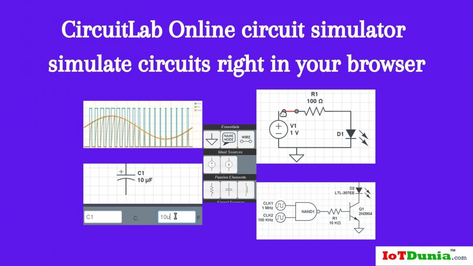
Circuit Lab simulator tool
Circuit Lab simulator is an in- browser schematic capture and circuit simulation software tool to help you double-quick design and dissect analog and digital electronics systems, frame and simulate circuits right in your browser.
- Design with our easy-to- use schematic editor.
- Analog & digital circuit simulations in seconds.
- Professional schematic PDFs, wiring plates, and plots.
- No installation needed! Launch it directly with one click. Launch it
Features of Circuit Lab Simulator
- Easy-to-use Power Tools
- Easy- wire mode lets you connect rudiments with fewer clicks and smaller frustration.
- Cross-window dupe/ paste lets you freely explore andre-mix corridor of public circuits from the CircuitLab community.
- Mixed-mode circuit simulation lets you pretend analog and digital factors side-by- side.
- SPICE-similar element models give you accurate results for nonlinear circuit goods.
- Mortal-friendly formats let you enter and display values compactly, just like you would on a paper schematic.
- Unit-apprehensive expression evaluation lets you plot arbitrary signals of interest, similar as discriminational signals or power dispersion.
- In- browser simulation and conniving lets you design and analyse speedy, making sure your circuit works ahead ever picking up a soldering iron.
- Unique circuit URLs let you fluently partake your work or ask for help online.
- Advanced simulation capabilities include frequence- sphere ( small signal) simulation, stepping circuit parameters through a range, arbitrary Laplace transfer function blocks, and more
- Common sense schematics let you name a knot”5V”and know that the simulator will do the right thing automatically, keeping your schematics compact and elegant.
- Quick- access figure box lets you draw introductory circuit savages snappily, while allowing access to a wide multifariousness of non-linear rudiments, feedback rudiments, digital/ mixed-mode factors, and custom delineation tools.
Getting Started with Circuit Lab simulation (online Circuit simulator)
The Basics of Circuit Simulation Lab
Build Mode
The editor always starts in Build Mode. You can switch to Simulate Mode by clicking the” Pretend” button along the bottom toolbar.
Ground
Every voltage in Circuit Lab is calculated relative to the ground (GND) knot, which is by description at 0 volts. This means that every circuit has to have at least one GND element, or the circuit won’t pretend.
Nodes
A knot in an electrical circuit is a place where two or further circuit rudiments meet.
Named Bumps
It’s frequently veritably useful (and good practice) to name certain bumps in your circuit. You can do this by using the Name Knot circuit element. A Name Knot can be dropped onto a line or directly onto any circuit element’s endpoint.
You can” connect”two bumps in your circuit by naming them the same thing. Giving two bumps the same name is original to drawing a line between two bumps.
Voltmeter and Ammeter
The Voltmeter and Ammeter rudiments can be used to display the voltage across or the current through the element on the schematic. You can double click a Voltmeter or Ammeter element to bring up the Parameters Box where you can elect” Show Voltage”or”Show Current”.
Mortal-Friendly Inputs
Circuit Lab allows you to use mortal-friendly metric prefixes for all of the numerical input boxes. For illustration, you can class”1k”for a resistance rather of codifying”1000″, or”22p” rather of”22e-12″ (which works too!)
Conniving Labors
Every simulation type has a separate Labors box where you can choose what you want to compass. When a simulation type is active (accordion box expanded) you can click on any line or Knot Name to plot the voltage at that knot.
DC Simulation
A DC simulation attempts to find a stable DC result of your circuit. When time- varying factors are present, their long- term geste is approached– for illustration, capacitors come open circuits, and inductors come short circuits
DC Sweep Simulation
A DC Sweep will compass the DC result of your circuit across different values of a parameter of a circuit element. You can sweep any numerical parameter of any circuit element in your circuit.
Time-Domain Simulation
A Time-Domain Simulation does a flash analysis of your circuit over a certain period of time.
Circuit Lab uses the dynamic model of the rudiments in your circuit work out the voltages and currents in your circuit at every time step. This means that it’s veritably important to choose an applicable time step for your flash simulation. However, the dynamic model will be inaccurate and the simulation could potentially look nothing like the real- life circuit would, If your time step is toolarge. However, your circuit may take too long to pretend, If your time step is too small.
A good rule of thumb when running a flash analysis is to pick your time step to be 10 times faster than than the fastest signal in your simulation. For illustration if the fastest source in your simulation is a 1 kHz sine surge, a good starting point would be to set the time step to0.1 m (0.1 milliseconds).
A flash simulation is similar to using an oscilloscope to make compliances about a circuit– observing the full, non-linear geste over a wide range of time scales.
Frequence- Sphere Simulation
Frequence Simulation does a small signal analysis of your circuit. The input can be any voltage source or current source. ( Note the input must be an element name, like”V1″, and not a knot name.) CircuitLab makes this chosen input a sine surge of magnitude 1 (by dereliction), and will sweep the frequence from the chosen launch frequence to the end frequence in Hertz.
Affair voltages and currents reported are the magnitude of the voltage or current relative to the input, which by dereliction is of magnitude 1. Still, and you measure a different knot’s voltage in frequence- sphere mode, the magnitude is a unitless gain (volts/ volt), If your input is a voltage source. Also, if your input is a current source, also any current you measure is a unitless gain (amps/ amp), and any voltage you measure is a transimpedance (volts/ amp).
There are three allowed forms of input source specifications
- V1-indicates a single input source named V1, with magnitude 1 and phase 0. This is original to”V1 1 0″.
- V1 10 90-indicates a single input source named V1, a complex phasor with magnitude 10 and phase 90 degrees.
- V1 10 90 V2 1 0-indicates two input sources V1 (magnitude 10, phase 90 degrees) and V2 ( magnitude 1, phase 0). Fresh sources beyond two can be included in the input list.
Plot Cursors and Math Functions
You may place up to two perpendicular and two vertical cursor lines on each plot. These cursor lines can be used to measure the absolute difference between any two points on the plot. The positions of the two cursors are also used to calculate a variety of calculation functions, including average, root- mean- squared (RMS), and integral values.
To apply one of the erected-in calculation functions to a particular trace, right click that trace in the legend and elect the computation you want from the environment menu. The result of the computation will be displayed in the word box in the lower- left corner of the plot. To remove an applied function, click the ‘X’that appears coming to it in the lower- left word box.
Smart Line
The smart cables point is meant to help the stoner when editing their schematic by anticipating a stoner’s intentions. When a stoner selects a particular line or element to edit, the system also bus-selects certain near factors that the stoner might want to edit as well.
Factors named in this way are stressed in blue while the element firstly named by the stoner remains stressed in red.
The smart cables point is available to all decoration members of CircuitLab (Hacker Lite plan and over). It’s presently not available to druggies of CircuitLab Free Edition.
Expressions
CircuitLab gives you the capability to produce and edit custom fine expressions to explore intriguing effects about your circuit. Expressions can be used in the affair boxes for all simulation types. The simplest expressions are peopled by CircuitLab by clicking on a knot or a circuit outstation while a simulation box is visible ( see conniving labors).
Circuit Rudiments
This runner contains some notes about how colorful circuit rudiments are modeled which may be useful for advanced druggies of CircuitLab.
Any circuit simulation is only as accurate as the model handed to the simulator.
Custom Device Models
The Custom Device Model point allows a stoner to produce a customized device model for certain circuit rudiments. The device model contains all the input parameters demanded to rightly pretend a specific part model from a specific manufacturer. Models can be saved, modified and used across all of that stoner’s circuits.
Custom Symbols
The Blockish Custom Symbol element allows a stoner to produce a customized blockish circuit element to be placed onto their schematic. While the part is presently not backed by a simulatable device model, the stoner is suitable to specify the size of the element as well as the number and placement of the legs
Simulation Troubleshooting
Circuit Lab is a veritably flexible tool with a wide range of operations. As with any general purpose stoner-programmable software, it’s possible to get into a broken state where the simulator is unfit to find a result to your circuit, or occasionally to indeed parse your schematic. Working through these crimes requires tolerance and experience. This companion covers some of the most common issues we see and explains how to break them.
For more reference: https//www.circuitlab.com/docs/simulation-troubleshooting/
System essentials
Circuit Lab pushes the envelope on in- browser calculation. Depending on your circuit, the simulator might be asked to break hundreds or thousands of contemporaneous non-linear equations. Your browser’s Javascript machine performance will have a significant effect on your simulation performance.
CircuitLab also uses ultramodern plates ways to allow for schematic editing and graphing in the browser. These ways are only supported in newer browser.
While we strive to support all ultramodern norms-biddable web browser, CircuitLab officially supports Google Chrome and Mozilla Firefox. Although we’re unfit to officially support them at this time, our druggies report success with Apple Safari and Opera.
Demo video:
Content reference and demo video credit: Circuitlab.com
Let us know your comment about Circuit lab simulator online circuit simulator for students in the comment section below.
See also: Free Online Circuit Simulator with Fritzing Software tool
Ready to Explore More? Let’s Build Smarter Together!
🔔 Subscribe to Our YouTube Channel » for IoT video Tutorials.
🌐 Start Learning IoT Basics Now » and What is IoT? – Introduction to IoT for Beginners on IoTDunia.com!
and Check out Top IoT Applications in Real World – Smart Use Cases 2025, IoT career guide 2025, Best Projects on IoT for Beginners
👉 Have questions? Drop them in the comments!
💡 Start small, stay curious, and make your world smarter—one device at a time.
Reference: To know more about Circuit Lab and how to use go through below